
SAN DIEGO Orca
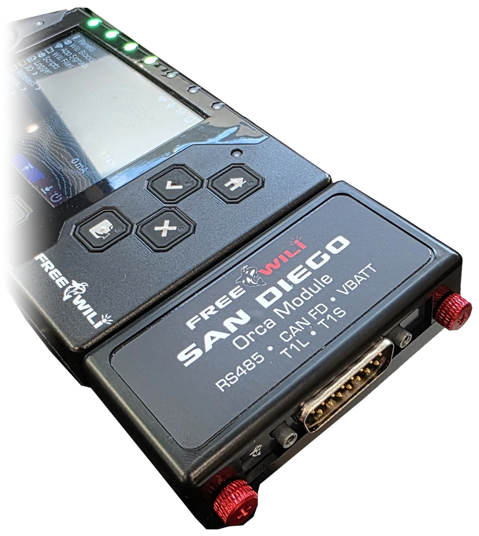
The SAN DIEGO Orca snaps onto your FREE-WILi 2 and adds RS485 and single-pair Ethernet (10BASE-T1L and 10BASE-T1S). It also routes FREE-WILi 2's existing internal CAN interface to the same rugged DB-15 connector. It supports CAN and ISO CAN FD through the host's SIC (Signal Improvement Capability) transceiver, with software-selectable CAN termination on FREE-WILi 2. This is the host's CAN channel; the Orca adds no CAN controller, transceiver, or termination components.
The DC V+ input is optional and is only needed if you want to power and charge FREE-WILi 2 from an external 5–60 V DC supply.* You can use the network interfaces without connecting DC V+. See power input specifications for wiring and supply details.
Industrial networks do not speak USB. They speak Modbus over RS485, CAN, CAN FD, and increasingly, single-pair Ethernet. SAN DIEGO Orca brings all of them to FREE-WILi 2 so you can sniff, script, simulate, and stress-test the same networks that run drives, sensors, robots, and entire production lines.
Plug it into the FREE-WILi extension connector, wire up the DB-15, and you are on the network with the same Python, Rust, C/C++ API, touchscreen, and onboard Linux workflow you already use.
Interfaces and power
- RS485
- 1x two-wire, half-duplex channel using an SP3485 transceiver, with switchable on-board termination, for Modbus, SAE J1708 (see J1708 wiring) and other RS485 protocols
- CAN / CAN FD
- Supports CAN and ISO CAN FD using FREE-WILi 2's internal SIC transceiver, routed to DB-15 pins 6 (CAN H) and 14 (CAN L); no additional CAN channel
- CAN termination
- Software-selectable on FREE-WILi 2; SAN DIEGO Orca uses the host's termination and adds no CAN termination components
- 10BASE-T1L
- 1x ADIN1110 interface with transformer coupling, for long-reach single-pair Ethernet up to 1 km with suitable cabling and link configuration
- 10BASE-T1S
- 1x LAN8651 interface for multidrop single-pair Ethernet, with selectable endpoint or midpoint termination and duplicated bus pins for through-wiring
- Digital I/O
- 1x direction-controlled, 5 V logic signal on DB-15 pin 13, via the on-board I/O expander
- DC V+ Input
- Optional 5–60 V DC input to power and charge FREE-WILi 2; positive on pin 15, with pin 8 as return*
- Connector
- All I/O routes through one rugged DB-15 harness interface
Power input specifications
Connect DC V+ only when you want to power and charge FREE-WILi 2 from an external DC supply. The network interfaces do not require this connection.
- Input voltage
- 5–60 V DC*
- Wiring / polarity
- Supply positive to DB-15 pin 15 (DC V+); supply negative to pin 8 (GND)
- Internal supply
- The on-board buck converter feeds the host's 5 V rail through the extension connector. Internal supply rating: 5 V at 2 A (10 W)
- Supply sizing
- Input current depends on input voltage, load, and conversion losses. The 2 A figure refers to the internal 5 V supply, not a fixed DC V+ input current. Allow voltage headroom above 5 V for a regulated 5 V rail under load
- Power path
- The internal 5 V output includes ideal-diode reverse-current blocking. This is not reverse-polarity protection at the DC V+ input; observe the input polarity
- Ground reference
- Pin 8 is the shared signal and power return, connected to host ground. The power input is not galvanically isolated
* DEF CON FREE-WILi 2 edition: the DC V+ power input does not function.
Who it is for
- Automation Engineers
- Engineers commissioning and troubleshooting PLCs, drives, and field devices on Modbus RS485, CAN, CAN FD, and single-pair Ethernet
- Security Research
- Researchers exploring industrial control networks with scriptable hardware workflows
- Industrial and IoT
- Developers bridging RS485 field devices and 10BASE-T1L sensor networks
- Makers and Students
- Learners building real industrial protocol skills on open hardware
Why FREE-WILi + SAN DIEGO
SAN DIEGO Orca brings RS485, 10BASE-T1L, 10BASE-T1S, and FREE-WILi 2's internal CAN and CAN FD interface with its SIC transceiver together on one DB-15 connector. Use them with the host's touchscreen, dual RP2350s, FPGA, onboard Linux, Python scripting, and wireless connectivity.
Log Modbus and CAN traffic to scripts, bridge it over WiFi, display live bus data on-screen, and automate full test sequences without carrying a laptop.
DB-15 pinout
Every bus and the DC supply input land on the module's male DB-15. The view below is what you see looking straight into the pins with the module label facing up: the wide row of eight is on top and pin 1 is at the top left.
| Pin | Signal | Description |
|---|---|---|
| 1 | T1S P | 10BASE-T1S positive |
| 2 | T1S N | 10BASE-T1S negative |
| 3 | T1L P | 10BASE-T1L positive |
| 4 | RS485 P | RS485 non-inverting line (A) |
| 5 | NC | Not connected |
| 6 | CAN H | FREE-WILi 2 internal CAN / CAN FD high, routed through the Orca |
| 7 | NC | Not connected |
| 8 | GND | Ground, signal and power return |
| 9 | T1S P | 10BASE-T1S positive, joined to pin 1 |
| 10 | T1S N | 10BASE-T1S negative, joined to pin 2 |
| 11 | T1L N | 10BASE-T1L negative |
| 12 | RS485 N | RS485 inverting line (B) |
| 13 | MISC DIO | Direction-controlled digital I/O, 5 V logic, via the on-board I/O expander |
| 14 | CAN L | FREE-WILi 2 internal CAN / CAN FD low, routed through the Orca |
| 15 | DC V+ | Optional 5–60 V DC positive input to power and charge FREE-WILi 2; return on pin 8* |
The 10BASE-T1S pair is brought out twice. Pins 1 and 9 are joined inside the module, as are pins 2 and 10, so a multidrop segment can come in on one pair and continue on the other.
RS485 uses a single pair for transmit and receive. Its switchable termination uses two 61.9 Ω resistors in series (123.8 Ω plus switch resistance). The T1S interface has separate endpoint and midpoint termination settings. The CAN pins share the host's existing CAN bus, with software-selectable CAN termination on FREE-WILi 2.
The DB-15 shell is coupled to ground through a 1 MΩ resistor and 10 nF capacitor; use pin 8 for the signal and power return.
SAE J1708 wiring
SAN DIEGO Orca can join an SAE J1708 heavy-vehicle bus, the network that J1587 runs on, and both transmit and receive at 9600 baud through its RS485 transceiver. J1708 uses the RS485 pair: pin 4 is J1708 A (+), pin 12 is J1708 B (−) and pin 8 is ground.
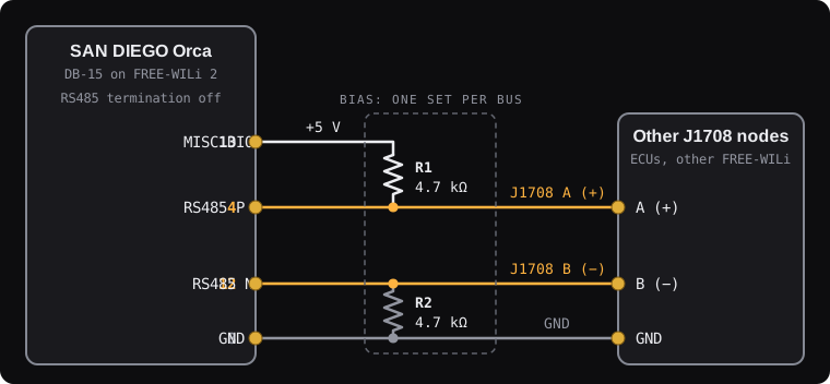
Unlike ordinary RS485, a J1708 transmitter only drives the wires to send a 0. To send a 1, and whenever the bus is idle, it lets go of the wires, and two bias resistors pull A above B so every receiver reads a 1. This lets two devices start talking at once without a conflict: a 0 always wins, and the device that sent a 1 sees the 0, stops and tries again. Without the bias resistors, an idle bus has no defined level.
With Bias 5V Pin 13 turned on, pin 13 supplies the 5 V for the pull-up, so a bench bus needs just the two resistors in the table below. Fit one set of bias resistors per bus. Vehicle J1708 networks are normally biased by the ECUs already on them; there, connect only A, B and GND.
In the FREE-WILi 2 SAE J1708 menu, turn on Enable, then turn on Bias 5V Pin 13 on the one FREE-WILi 2 the resistors are wired to. With the setting off, or while J1708 is not running, pin 13 is high impedance and never pulls low, so the pin 13 of several devices can share one wire. FREE-WILi 2 switches the Orca's RS485 termination off while J1708 runs, as J1708 is not terminated.
| Part | Value | Connects |
|---|---|---|
| R1 | 4.7 kΩ | Pin 13 (MISC DIO, 5 V) to pin 4 (J1708 A) |
| R2 | 4.7 kΩ | Pin 12 (J1708 B) to pin 8 (GND) |
J1708 requires FREE-WILi 2 firmware with SAE J1708 support.